


SKR2-C
AISIKAI
| Quantity: | |
|---|---|
Product Overview
SKR2-C series dual power ATS controller is made with the microprocessor as the core, which can precisely measure dual power voltages, make correct judgment and control outputs for occurred voltage abnormal (over voltage, under voltage, over frequency, under frequency, loss of phase, reverse phase sequence).
It realizes automatic and intelligent transfer of Automatic Transfer Switch.
SKR2-C ATS Controller integrates OLED display, digital communication, and realizes good human-computer interaction function.
| Item | SKR2-C | SKR2-CC |
AC Supply (LN170~V277V) | YES | YES |
Inputs (Fixed + Aux.) | 3+1 | 3+1 |
Outputs (Fixed + Aux.) | 5+1 | 5+1 |
| Genset Control | YES | YES |
| RS485 | NO | YES |
| LO NO Output | YES | YES |
— System can be set to: 3P4W, 3P3W, 2P3W, or 1P2W AC type;
— With MCU intelligent and precise monitoring and control;
— S1 master, S2 master can be set, auto transfer/restore, auto transfer, non-restore switch of master power is fitted;
— With Auto/Manual mode;
— With OFF mode, in which breaker close/open is inactive;
— System type can set to: S1 Mains S2 Mains, S1 Mains S2 Gen, S1 Gen S2 Mains;
— Measure and display 2-way 3-phase voltage, frequency and alarm status;
— Suit for two-breaking, one-breaking, no-breaking switch;
— Switch re-closing function is fitted;
— ATS can be configured to work through master and backup power supply, it can work normally as long as any power supply is normal;
— With RS485 isolated communication port (option), enables “remote control, remote measuring, remote communication, remote adjusting” function with ModBus communication protocol; ATS close/open can be controlled remotely;
— With overvoltage, undervoltage, overfrequency, underfrequency, loss of phase, reverse
phase sequence detection function, overvoltage/undervoltage threshold, overfrequency/underfrequency threshold can be set;
— Manual test is fitted, which can conduct genset start/stop;
— LED can intuitively display current ATS close status, power status, manual/auto/OFF mode and alarm;
— 2-way N wire isolated design.
Working conditions and installation modes
Category | Description |
Working Temperature | (-25+70)℃ |
Working Humidity | (20~95)%RH |
| Storage Temperature | (-30~+80)℃ |
Protection level | Front: IP65, when there is waterproof rubber ring installed between controller and the control panel. Rear: IP20 |
Insulation strength | Apply AC2.2kV voltage between high voltage terminal and low voltage terminal and the leakage current is not more than 3mA within 1min; insulation resistor: 100MΩ. |
| Weight | 0.57kg |
Specification
ltem | Content | |
Working voltage | AC power supply,voltage rangeAC(170V~277)V. | |
Power consumption | ≤5W(Standby mode:<2W) | |
AC voltage input | 3P4W(L-L) | AC170V~AC277V |
2P3W(A-B) | AC170V~AC277V | |
1P2W(L-N) | AC170V~AC277V | |
Rated frequency | Rated: 50/60Hz | |
Closing relay output | 10A AC250V Volts free output | |
| Auxiliary Relay Output | 10A AC250V Volts free output | |
Genset Crank Relay Output | 7A AC250V Volts free output | |
LONO Relay Output | 12A AC250V Passive output | |
LINK | AISIKAI special interface for program upgrade, parameter configuration | |
RS485 | Isolated, half-duplex, 2400/4800/9600/19200 baud rate can be set, Modbus-RTU communication protocol, max communication distance is 1000m. | |
Case dimensions | 143mm×124mm×49mm | |
Hole dimensions | 132mm×113mm | |
Design Standard | Meet GB/T14048.11-2016 and IEC/EN 60947-6-1 | |
Safety Reqiurement | Meet EN 61010-1 installation category (overvoltage type) III, 300V, pollution degree 2, altitude 3000m | |
Indicator Description
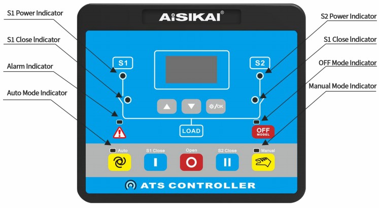
| Indicator | Description |
| S1 Power Indicator | Extinguishes when S1 power blackout; Illuminates when S1 power is normal; Flashes when S1 power is abnormal (under/over voltage, under/over frequency, loss of phase, reverse phase sequence). |
| S2 Power Indicator | Extinguishes when S2 power blackout; Illuminates when S2 power is normal; Flashes when S2 power is abnormal (under/over voltage, under/over frequency, loss of phase, reverse phase sequence). |
| S1 Close Indicator | Illuminates when S1 is closed; otherwise, it extinguishes. |
| S2 Close Indicator | Illuminates when S2 is closed; otherwise, it extinguishes. |
| Alarm Indicator | Flashes when there is alarm; Extinguishes when there is no alarm. |
| OFF Mode Indicator | Illuminates in OFF mode; extinguishes in other modes. |
| Auto Mode Indicator | Illuminates in AUTO mode; extinguishes in other modes. |
| Manual Mode Indicator | Illuminates in MANUAL mode; extinguishes in other modes. |
FAQ
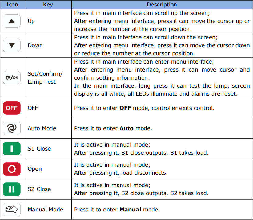
Manual Mode: User manually controls S1 Close, S2 Close, or Open commands.
Auto Mode: The controller automatically transfers between S1 and S2 based on power conditions and settings.
OFF Mode: The controller exits control, and the load is disconnected.
Q2: What does it mean if the S1 Power Indicator is flashing?
A: A flashing S1 Power Indicator means the S1 power source is abnormal (e.g., over/under voltage, over/under frequency, phase loss, or reverse phase sequence).
From the main menu, select "3. Start/Stop Genset," then choose "Genset Start" to output the start signal.
A: The generator will automatically start if the mains power (the source designated as utility) becomes abnormal, provided the system type is set to a mains/generator configuration (e.g., S1 Mains S2 Gen).
Q5: RS485 communication is not working. What could be wrong?
A:
Check if the A(+) and B(-) wires are correctly connected.
Verify the RS485 converter is functioning.
Check that the module address and baud rate settings in the controller match the master system's settings.
Q6: The ATS is not transferring automatically. What should I investigate?
A:
Check the ATS mechanism itself.
Verify the wiring between the controller and the ATS.
Ensure the "ATS Type" parameter matches the actual ATS hardware.
Check the power source voltage inputs and their "Available Delay" settings.
Project Upgrade in Peru: The customer replaced a disorganized and unstable electrical setup with the AISIKAI Electric adjustable MCCB solution, achieving cleaner wiring, more reliable protection, and improved system stability.
The Electronic MCCB with Built-in Electric Motorized Operating Mechanism solves the long-term reliability problems of traditional external motorized mechanisms, providing a more stable transmission.
The Load Isolation Switches (load disconnector) in this project provide visible isolation for maintenance, ensuring safe disconnection of the 5kV circuits during inspections and repairs to protect personnel and equipment.
Project Background:Vietnam's coastal ports and industrial parks are rapidly expanding. Due to frequent typhoons and rainy seasons, power interruptions are common. Many ports and cold chain warehouses require backup diesel generators and Automatic Transfer Switches (ATS) to ensure continuous operatio


