
Many people instinctively think, “Arcing is troublesome—wouldn’t it be better if there were no arc at all?”
In AC systems, however, the reality is exactly the opposite.
If the contacts were to separate and forcefully interrupt the current, the energy stored in the circuit inductance would be instantaneously transferred to stray capacitances. This can create dangerous overvoltages and may even lead to restrike phenomena.
A controlled arc behaves like a controllable switch: it allows the load energy to be released in an orderly manner and fed back to the power source, and then extinguishes at a favorable current zero crossing. Only after the breaker successfully withstands and dissipates the Transient Recovery Voltage (TRV) can the system be considered truly and safely restored.
The interruption process of a switching device can be described by the following four stages:
Contact separation → Arc initiation
Arc maintenance up to the “minimum arcing time”
Current zero → De-ionization → Arc extinction
Appearance and withstand of TRV → Transient decay to recovery voltage (RV)
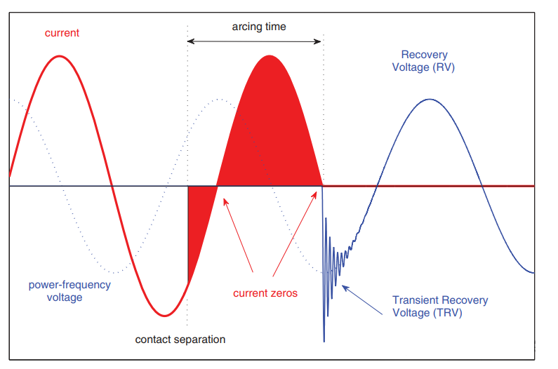
Figure 1: The four processes of interruption
When the contacts first begin to separate, tiny contact bridges still remain. The local current density becomes extremely high, causing the contact material to undergo melting, vaporization, and ionization. A plasma channel—an electric arc—is formed within the arc-quenching medium (air, oil, SF₆, or metal vapor in vacuum).
This process does not indicate loss of control. Instead, it transfers energy into a manageable conductive channel, preventing an immediate rise to excessive overvoltage. The purpose of this stage is to create sufficient contact gap and cooling conditions for the subsequent arc extinction.
During this stage, current continues to flow through the arc. The magnetic energy stored in the load—typically inductive—is gradually fed back to the power source through the arc.
Circuit breakers employ various arc-control techniques, such as:
Gas blast or oil flow to remove ionized media
Magnetic blowout to elongate and split the arc
Rapid diffusion of metal vapor in vacuum environments
Experience and testing show that a minimum arcing time and sufficient contact separation are essential for the breaker to be capable of achieving true interruption at the upcoming current zero.
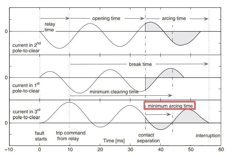
Figure 2: Minimum arcing time of a three-phase switching device
As the AC current approaches zero, if cooling and contact separation are adequate, the arc rapidly de-ionizes, the dielectric strength between the contacts recovers quickly, and the arc extinguishes at the zero crossing. The current is then truly interrupted.
It is important to note that interruption does not occur simply when the contacts separate. True interruption is achieved only at the moment of current zero with successful de-ionization. Whether interruption can be completed at the first zero crossing is closely related to the minimum arcing time in the previous stage, contact opening speed, flow-field design, and material selection.
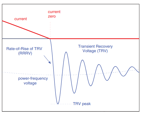
Figure 3: RRRV and TRV
After arc extinction, a Transient Recovery Voltage (TRV) immediately appears across the open contacts. This voltage is formed by the superposition of source-side and load-side components and typically exhibits a multi-frequency oscillatory waveform.
The circuit breaker must withstand, within standardized limits:
The Rate of Rise of Recovery Voltage (RRRV)
The peak TRV amplification factor
Otherwise, arc re-ignition may occur before full dielectric recovery. As the transient dissipates, the voltage returns to the power-frequency Recovery Voltage (RV). At this point, the interruption process is complete, and the equipment can be put back into service immediately.
Safe interruption by a circuit breaker depends on proper arc management and the ability to withstand TRV. When the arc is effectively controlled, energy is released smoothly, overvoltages are avoided, and the system can truly return to a safe and stable operating condition.

I am Eric, Electrical Engineer in AISIKAI Team. I will share technical articles on Switches, Circuit Breakers and other electrical devices. With 10 years of electric project experience, I am commited to provide professional electrical solutions.


