
Abstract: This article provides a detailed analysis of how to design a reliable three-phase Automatic Transfer Switch (ATS) system. By utilizing magnetic contactors, a phase failure relay, time relays, and DC control logic, the system achieves automatic generator startup upon mains power failure, load transfer, and safe automatic shutdown upon mains power restoration.
When designing industrial or commercial power backup systems, the Automatic Transfer Switch (ATS) is the core component.
This design scheme is compatible with three-phase 400V mains power and three-phase generators, employing both 230V AC control circuits and 12V DC (battery) control circuits for collaborative operation.
To construct this system, the following key electrical components are required:
Magnetic Contactors x2: Used to control the main power supply—one for the mains and one for the generator.
Phase Failure Relay (PFR): Used to monitor the three-phase voltage, phase sequence, and phase loss faults of the incoming mains supply.
Time Relays:
Mains side: Used for stabilization delay and switching interval protection.
Generator side (AC): Used for warm-up/loading delay.
Generator side (DC 12V): Used for startup delay, start failure detection, and shutdown cool-down delay.
Intermediate Relays: Including DPDT (Double Pole Double Throw) relays and 5-pin SPDT relays, used for signal conversion and logic interlocking.
Circuit Protection: Two-pole circuit breaker (for control circuit protection).
The primary task of the system is to monitor the status of the power grid.
Power Access and Monitoring: The three-phase mains supply is connected to the Phase Failure Relay (PFR). The PFR's Normally Open (NO) contact will only close if the phase sequence is correct and the voltage is normal (no under-voltage/over-voltage).
Stabilization Delay (Timer 1): After the PFR closes, Timer 1 is energized. A delay of 3-5 minutes is set here to ensure the mains supply is completely stable, preventing frequent switching during grid fluctuations.
Load Switching (Timer 2): After Timer 1 times out, the DPDT relay is activated. This subsequently triggers Timer 2 (set to 2-3 seconds), which maintains a "dead time" interval after the generator supply is disconnected and before the mains supply is connected, preventing power short circuits.
Contactor Engagement: Finally, the mains contactor coil (A1/A2) is energized, and the load is connected to the mains power.
Key Safety Interlock: The control circuit for the mains contactor must be wired in series with the Normally Closed (NC) auxiliary contact of the generator contactor to ensure they cannot engage simultaneously.
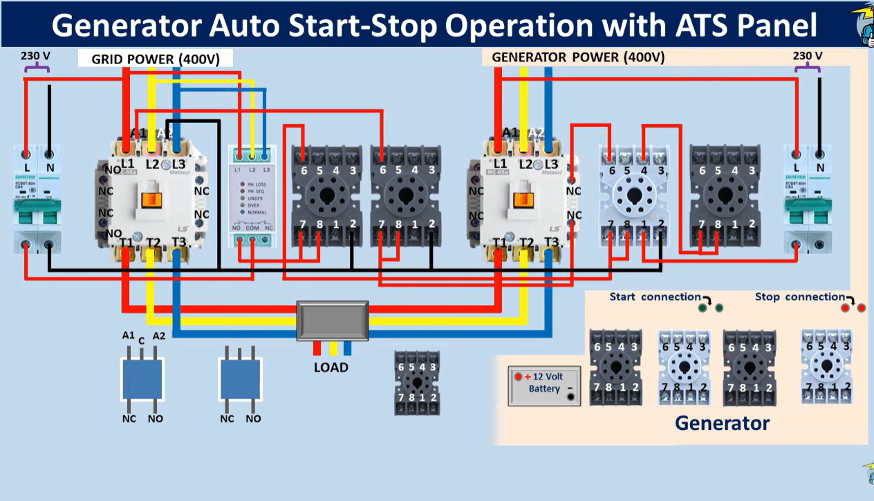
Figure 1: Wiring Diagram for Mains Monitoring and Control Circuit. Details the interlock wiring logic for the PFR, time relays, and contactor coils.
When the mains power is interrupted, the system utilizes the generator's 12V battery for control logic.
Fault Detection: The mains contactor opens, and its auxiliary Normally Closed (NC) contact closes, routing the 12V DC power.
Startup Debounce (Start Timer): Current flows into the start timer, set for a 2-3 second delay to prevent unnecessary generator starting during momentary power outages.
Execution of Start: After the delay, the start relay engages, connecting the generator's starting motor (Cranking). Simultaneously, the fuel solenoid is opened.
Cranking Disengagement: Once the generator establishes voltage (approx. 3-4 seconds), the generator-side SPDT relay operates, interrupting the starting motor circuit to protect the starter.
If the generator fails to start within 5-6 seconds, the start failure detection relay (Start Fail Timer) will operate, breaking the starting circuit. This prevents the starter motor from burning out due to prolonged operation and signals the need for manual inspection.
After the generator successfully starts, it should not immediately take the full load; a warm-up period is required.
Warm-up Delay: The generator output voltage triggers the AC time relay. A 10-15 second idle warm-up time is set to allow the engine to stabilize.
Power Transfer: After the delay, the generator contactor coil is energized and engages.
Interlock Protection: Similarly, the control line must pass through the Normally Closed (NC) auxiliary contact of the mains contactor to ensure electrical safety interlocking.
When the grid supply is restored, the ATS executes the following reset process:
Disconnect Generator Load:
The PFR detects the mains power is normal -> Delay ends -> DPDT relay operates -> Disconnects the generator contactor.
Connect Mains: After the 2-3 second safety interval, the mains contactor engages.
Cool-down Delay (Cool-down Timer): The generator is now unloaded but still running. The Normally Open (NO) auxiliary contact of the mains contactor closes, triggering the shutdown timer. A cool-down time of 3-5 minutes is recommended to allow the generator to dissipate heat under no-load conditions.
Execution of Stop: After the cooling delay, the stop relay operates, cutting the power to the fuel solenoid, and the generator shuts down.
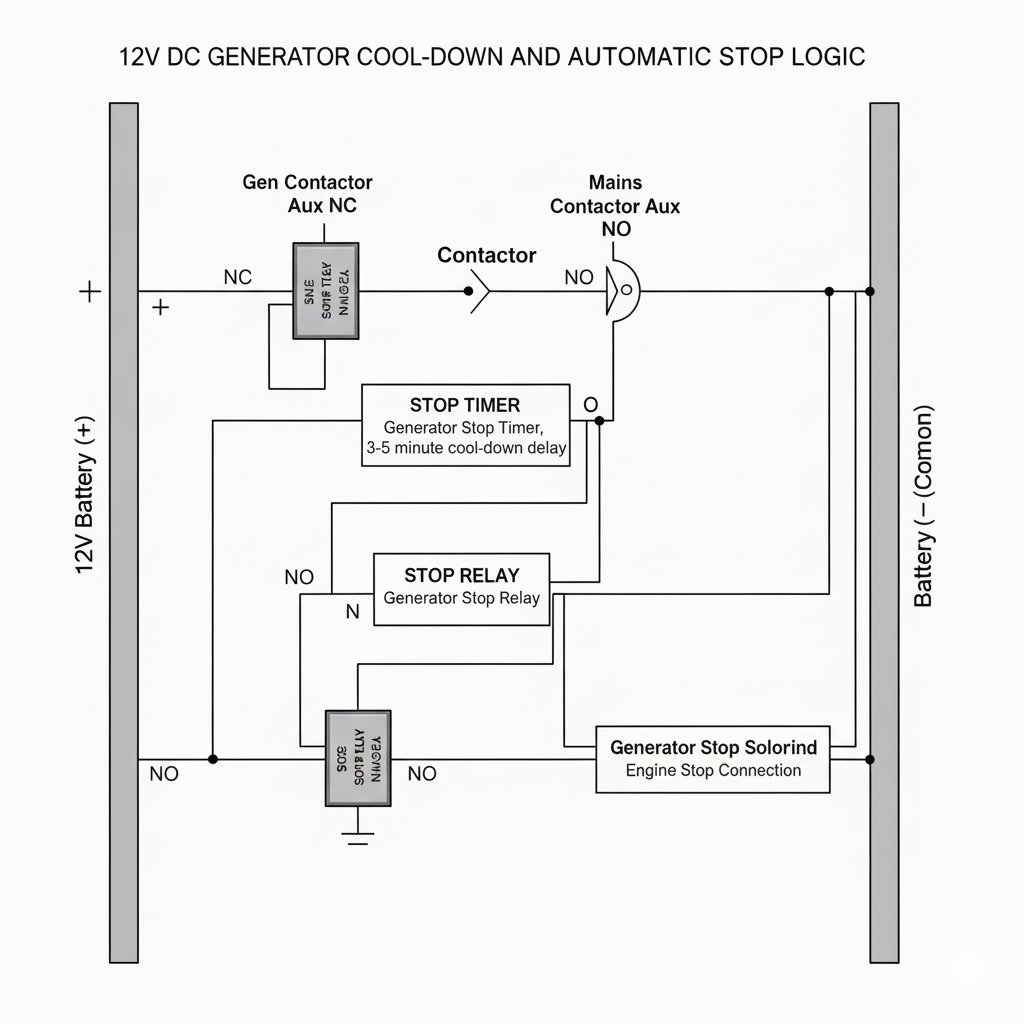
Figure 4: Generator Cool-down and Stop Control Logic Diagram. Analyzes how the mains contactor auxiliary contacts are used to achieve delayed shutdown.
Manual Mode: The system retains a circuit for manually starting or stopping the generator via a key or button, allowing for maintenance.
Breaker Protection: Be sure to manually switch off the generator control breaker during maintenance to prevent automatic accidental loading during a power outage.
Battery Maintenance: Regularly check the state of the 12V battery, as it is the core power source for the automatic starting logic.
Designing a comprehensive three-phase ATS system hinges on precise time-logic control and strict electrical interlocking. By properly configuring the phase failure relay, time relays, and intermediate relays, we not only achieve automatic power switching but also maximize the safety of the generator set and the downstream load equipment.
")
I am Eric, Electrical Engineer in AISIKAI Team. I will share technical articles on Switches, Circuit Breakers and other electrical devices. With 10 years of electric project experience, I am commited to provide professional electrical solutions.


